Reliable Test Equipment Manufacturer
Reliable Test Equipment Manufacturer
|
JFBTS Series Battery Testing System
Telephone:+86 13018663273
Mail:carleen@sailham.com
|

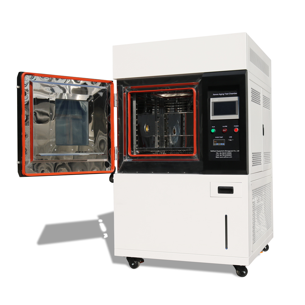
The JFBTS series battery testing system is a high-performance power supply testing product developed by Sailham Power Supply after years of in-depth research in the battery industry, in combination with customer needs and advanced technologies. This equipment has been widely used in various research institutions, university laboratories, and battery manufacturers, and has gained a good reputation.
The equipment supports standard charge-discharge tests, cycle charge-discharge tests, capacity tests, charge-discharge characteristic tests, charge-discharge efficiency tests, overcharge and overdischarge detection, power and energy tests, energy efficiency tests for individual batteries or battery groups; it supports intelligent generation of testing processes based on Excel and other condition data files and automatic completion of condition tests; it supports DC internal resistance tests based on the HPPC method, etc. The equipment can realize various complex process logics, has powerful data analysis capabilities, and supports connection with third-party devices such as BMS and integration, analysis, and processing of its testing data.
1.1. Equipment Features
The discharged energy is fed back to the power grid, achieving energy conservation and environmental protection;
The system adopts a modular structure, with high conversion efficiency and fast startup speed; it is easy to maintain and highly efficient;
It has protection functions such as reverse polarity, overcurrent, undercurrent, short circuit, AC or DC over/under voltage, over/under temperature, power failure, etc.;
Iaddition to the basic charging and discharging functions, it also includes reset procedures, reconnection startup, etc.;
It is equipped with a built-in cooling fan and a unique cooling air duct, which can effectively dissipate heat and automatically shut down to protect against overheating;
It has strong load adaptability and stability; it does not overcharge or undercharge, ensuring sufficient power and improving test accuracy.
The PC networking system can centrally control multiple devices and achieve unlimited data storage;
The upper computer software can adopt a master-slave mode to support simultaneous monitoring of multiple PCs during the test process, and can realize the control of test equipment by any PC in the local area network through permission conversion.
The account permission management is complete, and accounts with different permissions have different operation permissions.
It is equipped with a data analysis system, which can dynamically and real-time display curves of voltage, current, time, capacity, temperature, energy, power, etc., and the data can be exported in various forms such as Excel and text files.
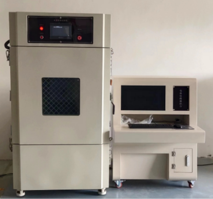
1.2. Hardware Structure
The JFBTS battery testing system consists of test channels, an upper computer control unit, a lower computer control system, and an auxiliary acquisition system. Structurally and functionally, it is mainly divided into five parts: power supply system, circuit switching system, sampling system, control communication system, and cooling system. Among them, the power supply system mainly includes power filter, AC/DC converter unit, and DC/DC bidirectional test power supply.
1.3. Software Structure
The software system in the JFBTS battery testing system mainly consists of the upper computer monitoring software, one or more middle computer control units, and multiple lower computer test power supplies. Among them, the upper computer software refers to the PC operation software of the testing system, through which it can control the operation of the testing system, view faults, perform equipment calibration, parameter setting, etc. The middle computers are used to control the process operation of each channel of the testing system, data recording, and forwarding and execution of upper computer commands, etc. The lower computers are responsible for receiving control commands sent by the middle computers, driving the hardware of the battery testing system, and outputting control voltages and currents.
The block diagram of the system software is shown in the following figure:
2.1 Technical Specifications
Table 2.1.1 Equipment Technical Specifications
System parameters | ||
Product model and specifications | ||
Number of channels | 4 channels | |
Control method | Each channel is independently controlled and supports parallel operation. | |
Discharge mode | Energy feedback | |
Main channel parameters | ||
Current | Output range | -300A~+300A |
Precision | ±0.05%FS | |
Resolution | 0.1mA | |
Voltage | Output range | Charging: 0 - 60V; Discharging: 6 - 60V |
Precision | ±0.05%FS | |
Resolution | 0.1mV | |
Power | Output range | 0~18000W |
Precision | ±0.1%FS | |
Resolution | 0.1W | |
Current response time | <10ms | |
Charge-discharge conversion time | <20ms | |
Work mode | ||
Work mode | Constant current, constant voltage, constant power, constant resistance, ramp charging and discharging, pulse, condition simulation, etc. | |
Termination/Transition Condition | Voltage, current, time, capacity, -ΔV, etc. | |
Technology / Process | ||
Looping Nesting | Maximum 10 floors | |
Number of cycles | Unlimited | |
Programmable steps | Maximum 999 | |
Recording method | Time interval, current interval, voltage interval. The operation steps can be set separately for the recording method. | |
Workstep time | ≤ 365 * 24 hours, minimum work step time 0.1 seconds | |
Data recording | ||
Minimum data record | 10mS | |
Data storage method | The data is saved in the form of a file. | |
Data export type | The data can be exported as EXCEL, TXT, chart files, etc. | |
Number of records | A single data file of 10 million. | |
Data analysis speed | 1 million operations per second (based on current mainstream computer configurations) | |
Data protection | When the equipment loses power, the running records that have not been uploaded will have power-off protection function. Once the power is restored, the system will automatically upload the records to ensure the completeness of the data. | |
Run offline | When the equipment is disconnected from the computer, the data has a recording buffer function, allowing the equipment to continue operating before reconnection to the computer. | |
Channel Safety Protection | When the channel is temporarily shut down due to safety protection, the software system automatically records the time and reason for this protection shutdown event. | |
Communication | ||
Communication method with the host computer | Ethernet | |
Communication interface | Network cable / LAN | |
Grid-side parameters | ||
Input power supply | Three-phase five-wire system, 380V ± 10% / 50Hz | |
Maximum input power | 80KW | |
Isolation form | High-frequency transformer | |
Appearance | ||
Reference dimensions | Width:750mm*Height:1900mm*Depth:850mm | |
Reference weight | 320KG | |
Color | According to the supplier's standards | |
Other | ||
Work environment temperature | -10℃-40℃ | |
Work environment humidity | 10% to 80% relative humidity, no condensation | |
Protection level | IP20 | |
(III) Introduction to Software Functions
3.1 System Overview
The software system of this battery testing equipment is based on a distributed control system consisting of an upper computer, a middle computer and a lower computer. One upper computer and one or more battery testers are connected through a network to achieve centralized network control and data processing. The upper computer software is a dedicated test management software that exchanges data with the middle computer via an Ethernet network. The middle computer controls the test power supply and auxiliary acquisition module of the lower computer to send commands and receive real-time operation data information from each lower computer. Operators can edit and set process programs and parameters through the upper computer test software, control the operation of each lower computer test power supply; the system can centrally display, store and query the working status and operation data of each lower computer test power supply; the test data curves support real-time refreshing, multi-channel comparison, and the content of the curves can be configured; statistical analysis of recorded data can be performed, and test record data can be exported for analysis.
3.2 System Functions
The software system can realize the operation control, data calibration and parameter configuration functions of the battery testing system. It can simulate the actual charging and discharging testing process of the battery during use, conduct automatic battery performance testing, and set test programs and parameters according to the test standards, and perform cycle life, capacity and other tests on the battery. The system has working modes such as current-limiting constant voltage charging, constant current discharging, constant power discharging, constant internal resistance discharging, cycling, and standing still. It has judgment conditions for time, voltage, current, stage capacity, cumulative charging capacity, cumulative discharging capacity, total capacity, power, resistance, energy (watt-hours), total temperature, single cell voltage, temperature, etc. It also has protection functions such as overcurrent, open circuit, upper and lower limit voltage, reverse polarity, overheating, power-off data saving, and automatic recovery upon power-on.
(Ⅳ) Safety and environmental protection requirements and environmental conditions requirements
4.1 Safety and Environmental Protection Requirements
Ensure that the working environment of the equipment is hygienic, and ensure that the materials used for equipment maintenance are promptly cleaned up;
Ensure that the cooling equipment of the device operates properly to maintain a good temperature condition, so that the working environment of the device will not become too hot due to accumulated heat;
Ensure that there is no battery liquid leakage, no water accumulation or acid accumulation, and no pollution in the equipment operation environment.
Ensure that the products in the equipment working environment are neatly arranged, and waste products are promptly cleaned and discharged, with clear safety passages;
The equipment operation environment should be equipped with fire safety facilities, and all necessary fire-fighting equipment should be available.
Require the equipment user to conduct necessary maintenance and repair of the equipment regularly, and conduct regular fire safety inspections of the usage environment.
4.2 Environmental Requirements
During operation, the ambient temperature around the equipment should not exceed 40℃ and should not be lower than -10℃. The recommended operating temperature is 25℃ ± 10℃. During storage and transportation, the ambient air temperature should not exceed 45℃ and should not be lower than -10℃.
The vertical inclination during installation should not exceed 5%.
The usage location must not contain explosive hazardous media. The surrounding media should not contain harmful gases that corrode metals or damage insulation, nor should there be conductive media. There should be no mold present.
The humidity of the working environment should not exceed 10% to 80% relative humidity and should not condense.
Phone
+86 13018663273
carleen@sailham.com